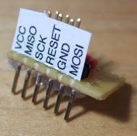
In order to do this, though, I need 8-9 output pins on the microcontroller which can be devoted to the output stage. As it happens, the ATTiny2313 should have enough, and is about the size of the ATTiny85 and one of the shift registers.
But enough about that. I wanted to play with shift registers, even if I wasn't going to use them in the digit decoder. To do that, I used an ATMega644 to drive a single 7-segment display. For input, I used four switches connected to a 74HC165N shift register. Output was via a 74HC565N shift register. Why shift registers and an ATMega644, which is wildly overpowered for this application, and which could read the switches and drive the 7-segment display directly? I didn't want to have to worry about microcontroller constraints (RAM size, etc), and wanted to concentrate on the shift registers.
This is the most complicated circuit I've ever breadboarded, and it just about fills up the breadboard. Everything from the ATMega644 to the left on the lower row is necessary support stuff (from right to left, the MCU, RS232 transceiver, and power switch. So basically support stuff takes up 1/3 of the board, leaving me the other 2/3. I'm going to need to switch to the big board soon. I'm tempted to leave the ATMega644 set up on this one so I don't have to rewire it and the transceiver whenever I want to use it. At the very least, I'll probably leave it set up until I verify whether I can make the hex decoder work.
Lessons learned (or relearned):
- Fuses are important. Not the kind that blow when there's too much current (though they're useful too), but the kind Atmel uses to configure AVR processors. The first one to bite me was the one that controls the JTAG interface. With it enabled (which it is by default), PC2-PC5 are dedicated to JTAG use. PC0 and PC1 function normally, which gave me one heck of a time trying to figure out why an early 3-LED circuit (one each on PC0-PC2) would only partially work.
- The other important fuses are the ones which control the oscillator. Atmel has a bewildering array of oscillator configuration options, involving 8 of the 19 fuses on the ATMega644. This AVR fuse calculator was very helpful.
- To write fuses, invoke avrdude as
avrdude -p part -U fusename:w:0xvalue:m - To read fuses to stdout, invoke it as
avrdude -p part -U fusename:r:-:h - I'd learned about aliasing while watching an EEVblog review of the "budget" Agilent 2000-series oscilloscope, and this time I got to see it in person. I wanted to verify that the processor was running properly at 16MHz, so I set the CKOUT pin, and ran it through my PCSU1000. I don't remember which Time/Div setting I was using, but I was seeing a stable output sine wave at about 1kHz, rather than 16MHz. Hilarity ensued until I remembered Dave's mention of aliasing, at which point I decreased the Time/Div setting. Low and behold, a 16MHz wave appeared. So that was exciting.
- You don't use the same variable for writing AVR ports as you do for reading them. PORTn for output, PINn for reading. Reading from PORTn, expecting to get input values, will only lead to sadness and dismay.


