Prompted by a question about the durability of board when faced with multiple insertions and removals into the edge connector, I decided to run a little test. I took one of the spare ALU boards (made by
Dorkbot PDX) and one of the
edge connectors I got from Jameco, and did 100 insertions. I took measurements after each batch of 10 insertions and removals. I didn't take pictures as I went, but I did take pictures at the end.
There was minor abrasion visible on the card edge after 10 cycles. Nothing alarming by any means, but you could see it if you tilted the board to the light just right. The abrasion got progressively more visible as the cycles continued; they're very visible at 100. I characterized the abrasion by measuring resistance. I figured if it got too bad, I'd see increased resistance. I took measurements in two places: First, from one end of the card edge pad to the other, and second from the card edge to the corresponding output pin on the edge connector.
There wasn't any noticeable change for the first 80 cycles. I'd consistently see about 0.4-0.5 ohms on the pad, and about 0.6 ohms from pad to pin. At the 90 cycle mark, I saw 1 ohm on the pad, and 2.2 ohms on from pad to pin. The 100 cycle test saw the edge connector resistance increase to 2.3 ohms. I took the measurements with my Extech EX330, using the stock pen-type probes.
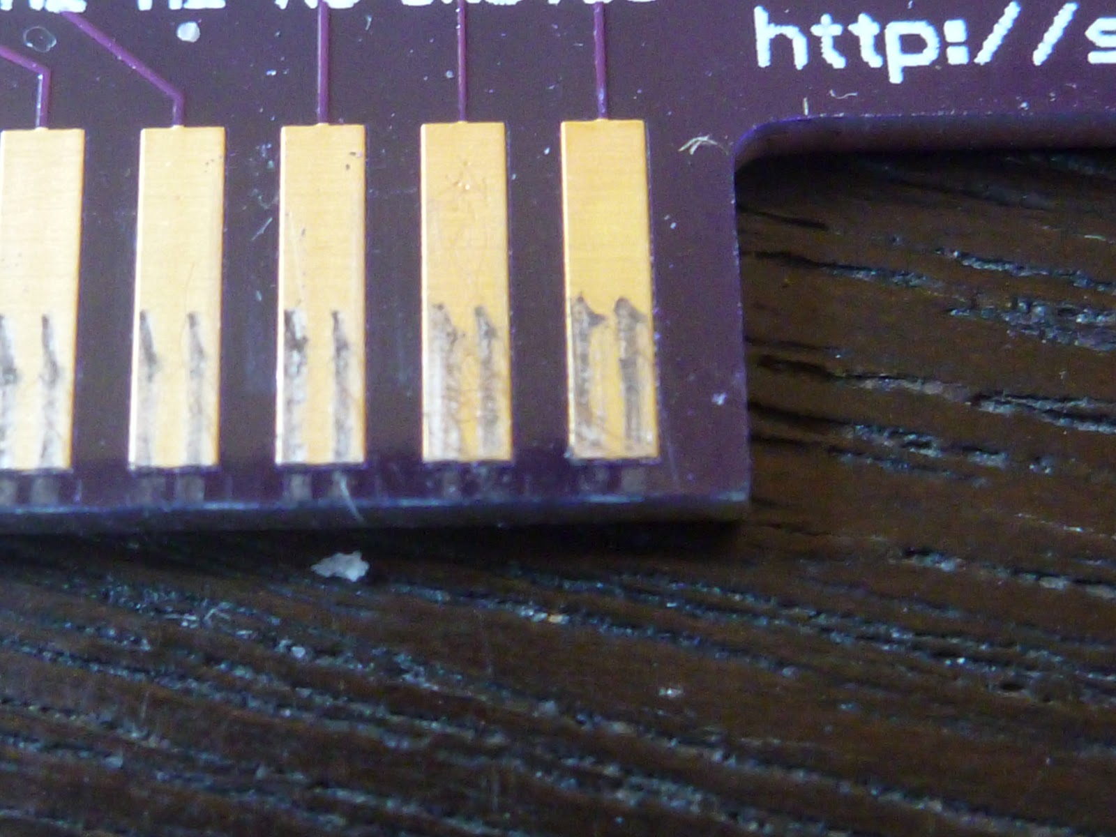
Here are pictures of the board after 100 cycles. I made a point of inserting the card into the connector the same way each time. The side with the heavy abrasions went into the connector first, so I guess it had the insertion as well as some amount of rotation when I put the other end of the card in.
I went at one of the pins with a hobby knife, and what I found underneath the gold(?) coating matched the abrasions. I'm assuming what that means is that the abrasions are the result of the coating being rubbed off, rather than some sort of transfer from the edge connectors.
The signals I'm sending across these edge connectors aren't terribly sensitive, so I'm guessing I needn't lose any sleep over the increase in resistance that comes from repeated insertion/removal cycles. If I do start to care (or need to care), it looks like I can reduce the impact of those cycles by pushing the board straight in, rather than one corner at a time. That'll increase the force on the board that's holding the edge connector, though. So many tradeoffs...